The Fuel tank was the first sub project that I decided to undertake. Tony Bingelis Book helped me on the basics of fiberglass work. I downloaded the Tank construction article by Marty Hammersmith along with the photographs. His instructions were followed by me more or less.
Three months were spent in tracking down local sources of fiberglass cloth, Polyurethane foam, and Vinyle Ester Resin. I obtained all these from the kind hearted Industry people at a reasonable cost. Cotton flakes and Glass bubbles were ordered from Wicks. My sister-in-law who lives in Bozeman, Montana helped me to bring them along with the AN Hardware when she visited Malaysia during that period. (Thanks Cheebu).
This was my first and probably the final attempt in building a foam fiberglass sandwich panel composite tank. It is yet to be completed. The accessories like Vent, Fuel outlet valve / flange and Float is yet to be installed. Most importantly sanding and final covering too awaits its time.
I could not get any of the polyurethane foams listed by Wicks or Aircraft Spruce, but I manage to locate a 1/2 inch think polyurethane foam which can stand up to 180 Centigrade. It was not very dense so I had to use a bit more glass bubbles to form the micro-slurry.
Two layers of 8 oz. matte fiber glass cloth are laid on every panel on either side with vinyl ester micro slurry before the first layer and clear resin after the first and second layers. The resin set within half an hour to touch and completely cured overnight.
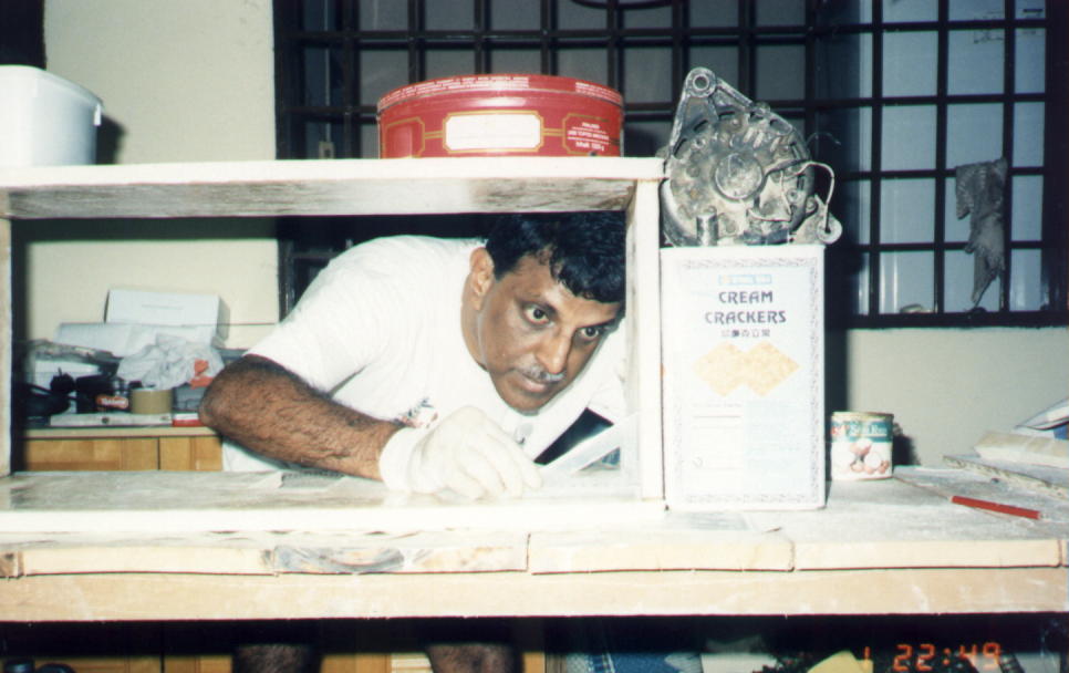
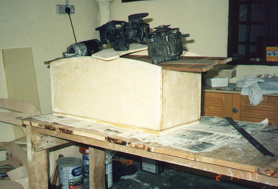
Attaching the Panels together was a simple balancing problem. Attempting to keep the process as simple as possible I used anything that I could reach to act as weights, clamps and stabilizing devices. However the result matched every measurement specified in the plans. Checking the angles at every point is essential while assembling these panels.
I was very worried that cats may come for a play on the structure before the joints set at night, but they did not. I guess the aroma of the resin kept them away.
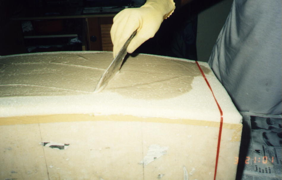
Coming to the top panel I must have have scratched my head for several
hours, as to how to lay a perfectly curved surface. I came up with the above
idea. Anything if possible, try to do it in place, to achieve perfect shape
or alignment. Two pieces of strings helped to hold the foam tightly over the
tapered top edge of the tank. I did the two layer of glass then pulled out
the strings and tied them over the glassed layer. Wonderful the result was
better than I expected.
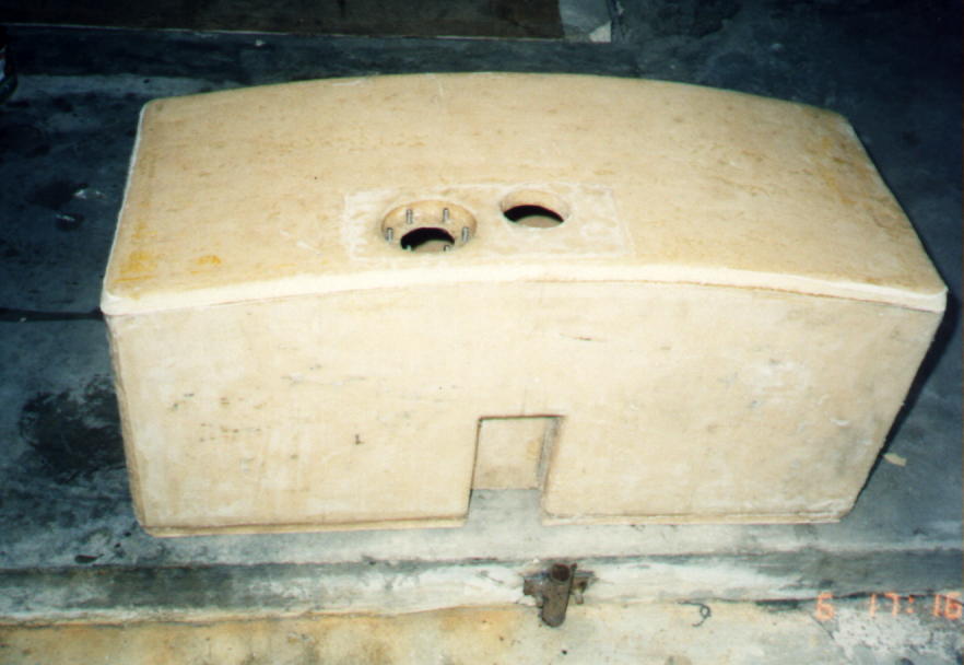
I preferred to have a removable float gauge in my tank, so I designed an opening to hold the float gauge assembly. The float will be screwed in place to the six stainless steel bolts that I floxed in. A fuel-proof gasket will sit between the tank and the float base. The fuel cap was also floxed in at the highest point on the tank, which I bought from Wicks. It sticks about 1/2 " above the tank. Remember to to lay an additional layer of glass over all areas where accessories are to be fitted for additional strength and support.
The gap between the tank upper surface and the forward deck skin will be about 1/2". So my tank cap will be flush with skin. I intend to device a sliding cover over the cap on the skin later to reduce drag.
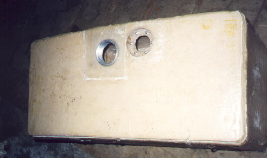
You will notice that the fuel cap has been floxed in, and the fuel gauge
float housing is done with six stainless steel bolts floxed in place. This
will allow removal and inspection of the gauge arm later. The bolt heads
exposed on the underside have been covered with bulbs of flox, to prevent
corrossion of any sort.
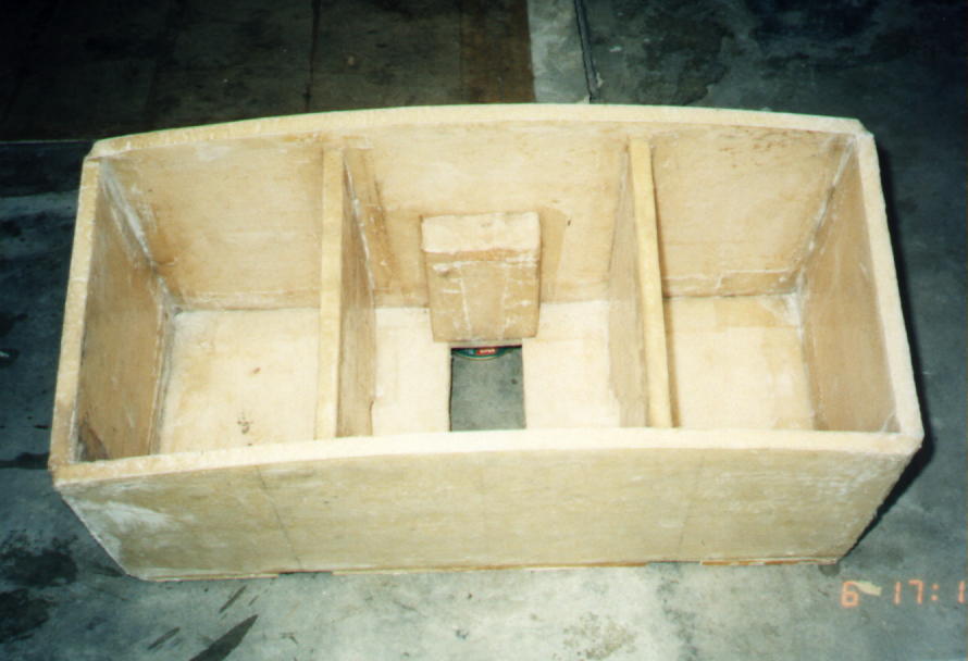
The baffles are in place. The whole thing looks unsightly I suppose. Wait
till the remaining effort of sanding, further coverings and painting is
completed. It will be sturdy, while looking good.
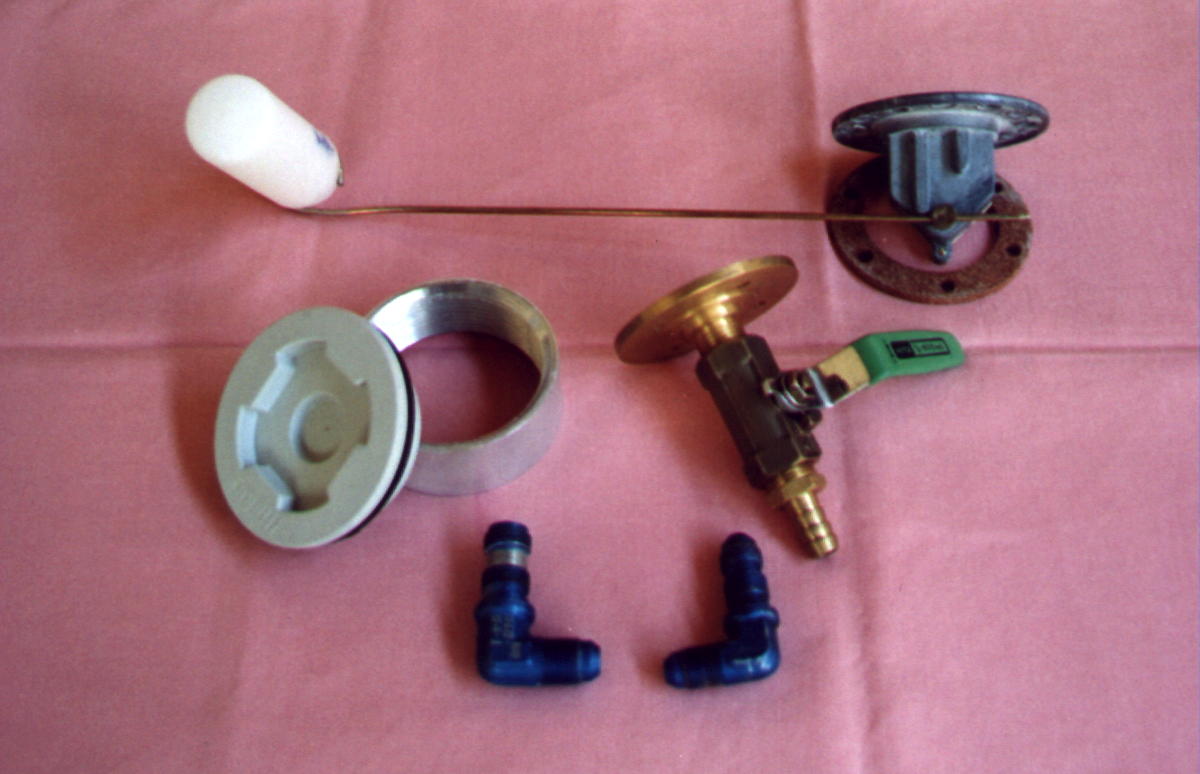
The above accessories remain to be married to the tank structure. The resin dried up before I could get the fuel outlet flange turned out of brass. My friend in India did this for me. All fuel lines are planned to be 1/4" diameter or larger i.e. 3/8". This work will definitely be completed before my first flight....Ha! Ha!.
Much discussions have taken place in the KRNet as well as in the SOOB List on the type of foam and resin to use for fuel tank construction. The essence of what I told myself while doing the tank are :-
Try to use Polyurethane foam which is fuel resistant.
Use Venyl Ester resin which is also fuel and additive resistant
Be generous on the amount of resin in lay-ups.
Reinforce joints with a liberal span of glass and resin, not just 1 inch on either side of the joint.
Sand all surfaces smooth inside the tank.
Pressure test till satisfaction, and have an independent audit before sealing the last panel.
Even the fumes have caused allergy among all in my family. It lasted for nearly for 5 months. Eating seafood caused rashes and skin lesions for all of us during that period, till it tapered off. Thank god, it was not permanent. Have a stand fan blowing away the fumes while working with this resin stuff. I intend to be extra careful during the next phase, but, let me tell you the stuff really smells good. I love it..